
FIGURE 2111.1
FIREPLACE AND CHIMNEY DETAILS

PROPOSAL
Note: This proposal was approved by the IBC Committee on 3/21/99 after tabling the issue twice to allow us to revise it. The revisions include 1) putting the fireplace section before the chimneys at the request of the Committee, 2) all the staff suggestions, 3) eliminating metal fireplaces and crickets inappropriate in this masonry chapter and 4) eliminating the controversial clearance to combustibles exceptions, which leaves us with no way to trim around a fireplace or chimney except with metal flashing but at least secured support from everybody except the NAHB and won approval for the proposal. We got masonry heaters in the IBC code for the first time, as well as all the ASTM referrences, seismic and flue sizing language we've been working on for the last few years in the IRC arena. It was an important victory with support from MACS, MFCA, CFLI, MHA, BIA, NCSG, NFPA, HPA, PCA and others.Delete Section 2111 FIREPLACES AND CHIMNEYS and replace with the attached language which should be identical to that in the International Residential Code (IRC) except that Section 1001.8.2 of the IRC referencing the IBC has been replaced with Sections 2111.8.2 and 2111.8.3 pertaining to chimneys for medium and high heat appliances.
Reason: Since both the IBC and IRC deal with the construction of fireplaces and chimneys the two codes should require the same things and be coordinated as much as possible.
2111.2 Footings and foundations. Foundations for masonry fireplaces and their chimneys shall be constructed of concrete or solid masonry at least 12 inches (305 mm) thick and shall extend at least 6 inches (153 mm) beyond the face of the fireplace or support wall on all sides. Footings shall be founded on natural undisturbed earth or engineered fill below frost depth. In areas not subjected to freezing, footings shall be at least 12 inches (305 mm) below finished grade.
2111.3 Seismic reinforcing. Masonry or concrete fireplaces shall be constructed, anchored, supported and reinforced as required in this chapter. In Seismic Design Category D, masonry and concrete fireplaces shall be reinforced and anchored as detailed in Section 2111.3.1, 2111.3.2, 2111.4 and 2111.4.1 for chimneys serving fireplaces. In Seismic Design Categories A, B or C, reinforcement and seismic anchorage is not required. In Seismic Design Categories E and F, masorny and concrete chimneys shall be reinforced in accordance with the requirements of Section 2101 through 2109.
2111.3.1 Vertical reinforcing. For fireplaces with chimneys up to 40 inches (1016 mm) wide, four No. 4 continuous vertical bars, anchored in the foundation, shall be placed in the concrete, or between wythes of solid masonry, or within the cells of hollow unit masonry, and grouted in accordance with Section 2103.10. For fireplaces with chimneys greater than 40 inches (1016 mm) wide, two additional No. 4 vertical bars shall be provided for each additional 40 inches (1016 mm) in width or fraction thereof.
2111.3.2 Horizontal reinforcing. Vertical reinforcement shall be placed enclosed within 1/4-inch ties, or other reinforcing of equivalent net cross-sectional area, spaced not to exceed 18-inches on center in concrete, or placed in the bed joints of unit masonry, at a minimum of every 18 inches (457 mm) of vertical height. Two such ties shall be provided at each bend in the vertical bars.
2111.4 Seismic anchorage. Masonry and concrete chimneys in Seismic Design Category D shall be anchored at each floor, ceiling or roof line more than 6 feet (1829 mm) above grade, except where constructed completely within the exterior walls. Anchorage shall conform to the following requirements:
2111.4.1 Anchorage. Two 3/16-inch by 1-inch (4.8 mm by 25 mm) straps shall be embedded a minimum of 12 inches (305 mm) into the chimney. Straps shall be hooked around the outer bars and extend 6 inches (153 mm) beyond the bend. Each strap shall be fastened to a minimum of four floor joists with two 1/2-inch (12.7 mm) bolts.
2111.5 Fireplace walls. Masonry fireplaces shall be constructed of solid masonry units, hollow masonry units grouted solid, stone, or concrete. When a lining of firebrick at least 2 inches (51 mm) in thickness or other approved lining is provided, the total minimum thickness of back and side walls shall be 8 inches (203 mm) of solid masonry, including the lining. The width of joints between firebricks shall not be greater than 1/4 inch (6.4 mm). When no lining is provided, the total minimum thickness of back and side walls shall be 10 inches (254 mm) of solid masonry. Firebrick shall conform to ASTM C 27 or C 1261 and shall be laid with medium-duty refractory mortar conforming to ASTM C 199.
2111.6 Steel fireplace units. Steel fireplace units incorporating a firebox liner of not less than 1/4 inch (6.4 mm) in thickness and an air chamber may be installed with masonry to provide a total thickness at the back and sides of not less than 8 inches (203 mm), of which not less than 4 inches (102 mm) shall be of solid masonry. Warm-air ducts employed with steel fireplace units of the circulating air type shall be constructed of metal or masonry.
2111.7 Lintel and throat. Masonry over a fireplace opening shall be supported by a lintel of non-combustible material. The minimum required bearing length on each end of the fireplace opening shall be 4 inches (102 mm). The fireplace throat or damper shall be located a minimum of 8 inches (203 mm) above the lintel.
2111.8 Smoke chamber. Smoke chamber walls shall be constructed of solid masonry units, stone or concrete. Corbeling of masonry units shall not leave unit cores exposed to the inside of the smoke chamber. When a lining of firebrick at least 2 inches (51 mm) thick, or a lining of vitrified clay at least 5/8 inch (16 mm) thick, is provided, the total minimum thickness of front, back and side walls shall be 6 inches (153 mm) of solid masonry, including the lining. Firebrick shall conform to ASTM C 27 or C 1261 and shall be laid with refractory mortar conforming to ASTM C 199. Where no lining is provided, the total minimum thickness of front, back and side walls shall be 8 inches (203 mm) of solid masonry. When the inside surface of the smoke chamber is formed by corbelled masonry the inside surface shall be parged smooth.
2111.8.1 Smoke chamber dimensions. The inside height of the smoke chamber, from the fireplace throat to the beginning of the flue, shall not be greater than the inside width of the fireplace opening. The inside surface of the smoke chamber shall not be inclined more than 45 degrees from vertical when prefabricated smoke chamber linings are used, or when the smoke chamber walls are rolled or sloped rather than corbeled. When the inside surface of the smoke chamber is formed by corbeled masonry, the walls shall not be corbeled more than 30 degrees from vertical.
2111.9 Hearth and hearth extension. Masonry fireplace hearths and hearth extensions shall be constructed of concrete or masonry, supported by non-combustible materials and reinforced to carry their own weight and all imposed loads. No combustible material shall remain against the underside of hearths and hearth extensions after construction.
2111.9.1 Hearth thickness. The minimum thickness of fireplace hearths shall be 4 inches (102 mm).
2111.9.2 Hearth extension thickness. The minimum thickness of hearth extensions shall be 2 inches (51 mm).
2111.11 Firebox dimensions. The firebox of a concrete or masonry fireplace shall have a minimum depth of 20 inches (508 mm). The throat shall not be less than 8 inches (203 mm) above the fireplace opening. The throat opening shall not be less than 4 inches (102 mm) in depth. The cross-sectional area of the passageway above the firebox, including the throat, damper and smoke chamber, shall not be less than the cross-sectional area of the flue.
2111.13 Mantel and trim. Woodwork or other combustible materials shall not be placed within 6 inches (153 mm) of a fireplace opening. Combustible material within 12 inches (305 mm) of the fireplace opening shall not project more than 1/8 inch (3.2 mm) for each 1-inch (25 mm) distance from such opening.
2111.14 Fireplace fire blocking. All spaces between fireplaces and floors and ceilings through which fireplaces pass shall be fire blocked with non-combustible material securely fastened in place. The fire blocking of spaces between wood joists, beams or headers shall be to a depth of 1 inch (25mm) and shall only be placed on strips of metal or metal lath laid across the spaces between combustible material and the chimney.
2111.15 Ash dump cleanout. Cleanout openings, when provided, shall be equipped with ferrous metal doors and frames constructed to remain tightly closed, except when in use. Cleanouts shall be accessible and located so that ash removal will not create a hazard to combustible materials.
2111.16 Exterior air. Factory-built or masonry fireplaces covered in this chapter shall be equipped with an exterior air supply to assure proper fuel combustion unless the room is mechanically ventilated and controlled so that the indoor pressure is neutral or positive.
2111.16.2 Masonry fireplaces. Listed combustion air ducts for masonry fireplaces shall be installed according to the terms of their listing and manufacturer's instructions.
2111.16.3 Exterior air intake. The exterior air intake shall be capable of providing all combustion air from the exterior of the dwelling. The exterior air intake shall not be located within the garage, attic, basement or crawl space of the dwelling nor shall the air intake be located at an elevation higher than the firebox. The exterior air intake shall be covered with a corrosion-resistant screen of 1/4-inch (6.4 mm) mesh.
2111.16.4 Clearance. Unlisted combustion air ducts shall be installed with a minimum 1-inch (25 mm) clearance to combustibles for all parts of the duct within 5 feet (1524 mm) of the duct outlet.
2111.16.5 Passageway. The combustion air passageway shall be a minimum of 6 square inches (3870 mm2) and not more than 55 square inches (0.035 m2) except that combustion air systems for listed fireplaces or for fireplaces tested for emissions shall be constructed according to the fireplace manufacturer's instructions.
2111.16.6 Outlet. The exterior air outlet is permitted to be located in the back or sides of the firebox chamber, or within 24 inches (610 mm) of the firebox opening on or near the floor. The outlet shall be closable and designed to prevent burning material from dropping into concealed combustible spaces.
| ITEM | LETTER | REQUIREMENTS | SECTION |
|---|---|---|---|
| Hearth and hearth extension thickness | A | 4-inch minimum thickness for hearth. 2-inch minimum thickness for hearth | 2111.9 |
| Hearth extension (each side of opening) | B | 8 inches for fireplace opening less than 6 square feet. 12 inches for fireplace opening greater than or equal to 6 square feet. | 2111.10 |
| Hearth extension (front of opening) | C | 16 inches for fireplace opening less than 6 square feet. 20 inches for fireplace opening greater than or equal to 6 square feet. | 2111.10 |
| Firebox dimensions | D | 20-inch minimum firebox depth. 12-inch minimum firebox depth for Rumford fireplaces. | 2111.11 |
| Hearth and hearth extension reinforcing | E | Reinforced to carry its own weight and all imposed loads | 2111.9 |
| Thickness of wall of firebox | F | 10 inches solid masonry or 8 inches where firebrick lining is used. | 2111.5 |
| Distance from top of opening to throat | G | 8 inches minimum. | 2111.7 |
| Smoke chamber Wall thickness Dimensions | H | 6 inches lined; 8 inches unlined. Not taller than opening width; walls not inclined more than 45 degrees from vertical for prefabricated smoke chamber linings or 30 degrees from vertical for corbeled masonry. | 2111.8 |
| Chimney vertical reinforcing | I | Four No. 4 full-length bars for chimney up to 40 inches wide. Add two No. 4 bars for each additional 40 inches or fraction of width, or for each additional flue. | 2111.3.1 |
| Chimney horizontal reinforcing | J | 1/4-inch ties at each 18 inches, and two ties at each bend in vertical steel. | 2111.3.2 |
| Fireplace lintel | K | Non-combustible material with 4-inch bearing length of each side of opening. | 2111.7 |
| Chimney walls with flue lining | L | 4-inch-thick solid masonry with 5/8-inch fireclay liner or equivalent. 1/2-inch grout or airspace between fireclay liner and wall. | 2111.6 2111.7 |
| Effective flue area (based on area of fireplace opening and chimney) | M | See Section 2113.12 | 2113.12 |
| Clearances From chimney From fireplace Combustible trim or materials Above roof | N | 2 inches interior, 1 inch exterior or 12" from lining. 2 inches back or sides or 12" from lining. 6 inches from opening. 3 feet above roof penetration, 2 feet above part of structure within 10 feet. | 2111.14 2111.11 2111.12 2111.5 |
| Anchorage Strap Number Embedment into chimney Fasten to | O | 3/16 inch by 1 inch. Two 12 inches hooked around outer bar with 6-inch extension. 4 joists.feet. Two 1/2-inch diameter. | 2111.4 |
| Footing Thickness Width | P | 12-inch minimum. 6 inches each side of fireplace wall. | 2111.2 |
FIGURE 2111.1
FIREPLACE AND CHIMNEY DETAILS
2112.2 Installation. Masonry Heaters shall be listed or installed in accordance to ASTM E-1602
2112.3 Seismic reinforcing. Seismic reinforcing shall not be required within the body of a masonry heater whose height is equal to or less than 2.5 times it's body width and where the masonry chimney serving the heater is not supported by the body of the heater. Where the masonry chimney shares a comon wall with the facing of the masonry heater, the chimney portion of the structure shall be reinforced in accordance with Section 2113.
2112.4 Masonry heater clearance. Wood or other combustible framing shall not be placed within 4 inches (102 mm) of the outside surface of a masonry heater, provided the wall thickness of the firebox is not less than 8 inches (203 mm) and the wall thickness of the heat exchange channels is not less than 5 inches (127 mm). A clearance of at least 8 inches (203 mm) shall be provided between the gas tight capping slab of the heater and a combustible ceiling. The required space between the heater and combustible material shall be fully vented to permit the free flow of air around all heater surfaces.
2113.2 Footings and foundations. Foundations for masonry chimneys shall be constructed of concrete or solid masonry at least 12 inches (305 mm) thick and shall extend at least 6 inches (153 mm) beyond the face of the foundation or support wall on all sides. Footings shall be founded on natural undisturbed earth or engineered fill below frost depth. In areas not subjected to freezing, footings shall be at least 12 inches (305 mm) below finished grade.
2113.3 Seismic reinforcing. Masonry or concrete chimneys shall be constructed, anchored, supported and reinforced as required in this chapter. In Seismic Design Category D, masonry and concrete chimneys shall be reinforced and anchored as detailed in Section 2113.3.1 and 2113.3.2. In Seismic Design Categories A, B or C, reinforcement and seismic anchorage is not required. In Seismic Design Categories E and F, masorny and concrete chimneys shall be reinforced in accordance with the requirements of Section 2101 through 2109.
2113.3.1 Vertical reinforcing. For chimneys up to 40 inches (1016 mm) wide, four No. 4 continuous vertical bars, anchored in the foundation, shall be placed in the concrete, or between wythes of solid masonry, or within the cells of hollow unit masonry, and grouted in accordance with Section 2103.10. Grout shall be prevented from bonding with the flue liner so that the flue liner is free to move with thermal expansion. For chimneys greater than 40 inches (1016 mm) wide, two additional No. 4 vertical bars shall be provided for each additional 40 inches (1016 mm) in width or fraction thereof.
2113.3.2 Horizontal reinforcing. Vertical reinforcement shall be placed enclosed within 1/4-inch ties, or other reinforcing of equivalent net cross-sectional area, spaced not to exceed 18-inches on center in concrete, or placed in the bed joints of unit masonry, at a minimum of every 18 inches (457 mm) of vertical height. Two such ties shall be provided at each bend in the vertical bars.
2113.4 Seismic anchorage. Masonry and concrete chimneys and foundations in Seismic Design Category D shall be anchored at each floor, ceiling or roof line more than 6 feet (1829 mm) above grade, except where constructed completely within the exterior walls. Anchorage shall conform to the following requirements:
2113.4.1 Anchorage. Two 3/16-inch by 1-inch (4.8 mm by 25 mm) straps shall be embedded a minimum of 12 inches (305 mm) into the chimney. Straps shall be hooked around the outer bars and extend 6 inches (153 mm) beyond the bend. Each strap shall be fastened to a minimum of four floor joists with two 1/2-inch (12.7 mm) bolts.
2113.5 Corbeling. Masonry chimneys shall not be corbeled more than half of the chimney's wall thickness from a wall or foundation, nor shall a chimney be corbeled from a wall or foundation which is less than 12 inches (305 mm) in thickness unless it projects equally on each side of the wall, except that on the second story of a two-story dwelling, Corbeling of chimneys on the exterior of the enclosing walls may equal the wall thickness. The projection of a single course shall not exceed one-half the unit height or one-third of the unit bed depth, whichever is less.
2113.6 Changes in dimension. The chimney wall or chimney flue lining shall not change in size or shape within 6 inches (153 mm) above or below where the chimney passes through floor components, ceiling components or roof components.
2113.7 Offsets. Where a masonry chimney is constructed with a fireclay flue liner surrounded by one wythe of masonry, the maximum offset shall be such that the centerline of the flue above the offset does not extend beyond the center of the chimney wall below the offset. Where the chimney offset is supported by masonry below the offset in an approved manner, the maximum offset limitations shall not apply. Each individual corbeled masonry course of the offset shall not exceed the projection limitations specified in Section 2113.2.
2113.8 Additional load. Chimneys shall not support loads other than their own weight unless they are designed and constructed to support the additional load. Masonry chimneys shall be permitted to be constructed as part of the masonry walls or concrete walls of the building.
2113.9 Termination. Chimneys shall extend at least 2 feet (610 mm) higher than any portion of the building within 10 feet (3048 mm), but shall not be less than 3 feet (914 mm) above the point where the chimney passes through the roof.
2113.10 Wall thickness. Masonry chimney walls shall be constructed of concrete, solid masonry units, or hollow masonry units grouted solid with not less than 4 inches nominal thickness.
2113.11 Flue lining (material). Masonry chimneys shall be lined. The lining material shall be appropriate for the type of appliance connected, according to the terms of the appliance listing and manufacturer's instructions.
2113.11.1 Residential-type appliances (general). Flue lining systems shall comply with one of the following:
2. Listed chimney lining systems complying with UL 1777, Chimney Liners.
3. Factory-built chimneys or chimney units listed for installation within masonry chimneys.
2113.11.1.1 Flue Linings for Specific Appliances. Flue linings other than covered in Section 2113.8.1 intended for use with specific appliances, shall comply with Sections 2113.11.1.2 through 2113.11.1.4 and Sections 2113.11.2 and 2113.11.3
2113.11.1.2 Gas Appliances Flue lining systems for gas appliances shall be in accordance with the International Fuel Gas Code.
2113.11.1.3 Pellet fuel-burning appliances Flue lining and vent systems for use in masonry chimneys with pellet fuel-burning appliances shall be limited to the following:
1) Flue lining systems complying with Section 2113.11.1
2) Pellet vents listed for installation within masonry chimneys (see Section 2113.11.1.5 for marking.)
2113.11.1.4 Oil fired appliances approved for use with L-vent Flue lining and vent systems for use in masonry chimneys with oil fired appliances approved for use with Type L vent shall be limited to the following:
1) Flue lining systems complying with Section 2113.11.1
2) Listed chimney liners complying with UL 641. (see Section 2113.11.1.5 for marking.)
2113.11.1.5 Notice of usage When a flue is relined with a material not complying with Section 2113.11.1 the chimney shall be plainly and permanently identified by a label attached to a wall ceiling or other conspicuous location adjacent to where the connector enters the chimney. the label shall include the following message or equivalent language. "This chimney is for use only with [Type or category] of appliance that burn [type of fuel]. Do not connect other types of appliances."
2113.11.2.2 Construction. Chimneys for medium-heat appliances shall be constructed of solid masonry units or of concrete with walls a minimum of 8 in. (203 mm) thick, or with stone masonry a minimum of 12 in. (305 mm) thick.
2113.11.2.3 Lining. Concrete and masonry chimneys shall be lined with an approved medium-duty refractory brick, a minimum of 4-1/2 in. (114 mm) thick laid on the 4-1/2 inch bed (114 mm) in an approved medium-duty refractory mortar. The lining shall start 2 feet (610 mm) or more below the lowest chimney connector entrance. Chimneys terminating 25 feet (7620 mm) or less above a chimney connector entrance shall be lined to the top.
2113.11.2.4 Multiple passageway. Concrete and masonry chimneys containing more than one passageway shall have the liners separated by a minimum 4-inch-thick (102 mm) concrete or solid masonry wall.
2113.11.2.5 Termination height. Concrete and masonry chimneys for medium-heat appliances shall extend a minimum of 10 feet (3048 mm) higher than any portion of any building within 25 feet (7620 mm).
2113.11.2.6 Clearance. A minimum clearance of 4 in. (102 mm) shall be provided between the exterior surfaces of a concrete or masonry chimney for medium-heat appliances and combustible material.
2113.11.3.2 Construction. Chimneys for high-heat appliances shall be constructed with double walls of solid masonry units or of concrete, each wall to be a minimum of 8 in. (203 mm) thick with a minimum air space of 2 in. (51 mm) between the walls.
2113.11.3.3 Lining.The inside of the interior wall shall be lined with an approved high-duty refractory brick, a minimum of 4-1/2 in. (114 mm) thick laid on the 4-1/2 inch bed (114 mm) in an approved high-duty refractory mortar. The lining shall start at the base of the chimney and extend continuously to the top.
2113.11.3.4 Termination height.Concrete and masonry chimneys for high-heat appliances shall extend a minimum of 20 feet (6096 mm) higher than any portion of any building within 50 feet (15240 mm).
2113.11.3.5 Clearance. Concrete and masonry chimneys for high-heat appliances shall have approved clearance from buildings an structures to prevent overheating combustible materials, to permit inspection and maintenance operations on the chimney, and to prevent danger of burns to persons.
Fireclay flue liners shall be laid in medium-duty refractory mortar conforming to ASTM C-199 with tight mortar joints left smooth on the inside and installed to maintain an air space or insulation not to exceed the thickness of the flue liner separating the flue liners from the interior face of the chimney masonry walls. Flue lining shall be supported on all sides. Only enough mortar shall be placed to make the joint and hold the liners in position.
2113.13.1 Listed materials. Listed materials used as flue linings shall be installed in accordance with the terms of their listings and manufacturer's instructions.
2113.13.2 Space around lining. The space surrounding a chimney lining system or vent installed within a masonry chimney shall not be used to vent any other appliance.
2113.16 Flue area (masonry fireplace). Flue sizing for chimneys serving fireplaces shall be in accordance with Sections 2113.12.1 or 2113.12.2
2113.16.1 Round chimney flues shall have a minimum net cross-sectional area of at least 1/12 of the fireplace opening. Square chimney flues shall have a minimum net cross-sectional area of at least 1/10 of the fireplace opening. Rectangular chimney flues with an aspect ratio less than 2 to 1 shall have a minimum net cross-sectional area of at least 1/10 of the fireplace opening. Rectangular chimney flues with an aspect ratio of 2 to 1 or more shall have a minimum net cross-sectional area of at least 1/8 of the fireplace opening.
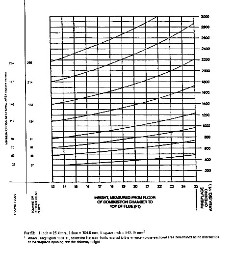
2113.16.2 The minimum net cross-sectional area of the flue shall be determined in accordance with Figure 2113.12. A flue size providing at least the equivalent net cross-sectional area shall be used. Cross-sectional areas of clay flue linings are provided in Tables 2113.12a and 2113.12b or as provided by the manufacturer or as measured in the field. The height of the chimney shall be measured from the firebox floor to the top of the chimney flue.
| FLUE SIZE, INSIDE DIAMETER (inches) | CROSS-SECTIONAL AREA (square inches) |
|---|---|
| 6 | 28 |
| 7 | 38 |
| 8 | 50 |
| 10 | 78 |
| 10-3/4 | 90 |
| 12 | 113 |
| 15 | 176 |
| 18 | 254 |
| FLUE SIZE, OUTSIDE DIMENSIONS (inches) | CROSS-SECTIONAL AREA (square inches) |
|---|---|
| 4-1/2 x 13 | 34 |
| 7-1/2 x 7-1/2 | 37 |
| 8-1/2 x 8-1/2 | 47 |
| 7-1/2 x 11-1/2 | 58 |
| 8-1/2 x 13 | 74 |
| 7-1/2 x 15-1/2 | 82 |
| 11-1/2 x 11-1/2 | 91 |
| 8-1/2 x 17-1/2 | 101 |
| 13 x 13 | 122 |
| 11-1/2 x 15-1/2 | 124 |
| 13 x 17-1/2 | 165 |
| 15-1/2 x 15-1/2 | 168 |
| 15-1/2 x 19-1/2 | 214 |
| 17-1/2 x 17-1/2 | 226 |
| 19-1/2 x 19-1/2 | 269 |
| 20 x 20 | 286 |
2113.17 Inlet. Inlets to masonry chimneys shall enter from the side. Inlets shall have a thimble of fireclay, rigid refractory material or metal that will prevent the connector from pulling out of the inlet or from extending beyond the wall of the liner.
2113.18 Masonry chimney cleanout openings. Cleanout openings shall be provided within 6 inches (153 mm) of the base of each flue within every masonry chimney. The upper edge of the cleanout shall be located at least 6 inches (153 mm) below the lowest chimney inlet opening. The height of the opening shall be at least 6 inches (153 mm). The cleanout shall be provided with a non-combustible cover.
[The Rumford Store]
[Rumford Picture Gallery]
[Specifications]
[Plans & Instructions]
[Manufacturers]
[Dealers]
[Architects]
[Builders]
[Masons]
[Sweeps]
[Associations]
[Masonry Chimneys]
[Masonry Heaters]
[Training]
[links]
[search]
[Superior Clay Corporation]

Buckley Rumford Fireplace Home Page
Copyright 1996 - 1999 Jim Buckley
All rights reserved.