CHIMNEYS AND FIREPLACES
|
MASONRY FIREPLACES
R1001.2 Footings and foundations. Footings for masonry fireplaces and their chimneys shall be constructed of concrete or solid masonry at least 12 inches (305 mm) thick and shall extend at least 6 inches (152 mm) beyond the face of the fireplace or foundation wall on all sides. Footings shall be founded on natural, undisturbed earth or engineered fill below frost depth. In areas not subjected to freezing, footings shall be at least 12 inches (305 mm) below finished grade.
R1001.3.2 Horizontal reinforcing. Vertical reinforcement shall be placed within 1/4-inch (6 mm) ties, or other reinforcing of equivalent net cross-sectional area, placed in the bed joints according to Section R607 at a minimum of every 18 inches (457 mm) of vertical height. Two such ties shall be installed at each bend in the vertical bars.
|
R1001.5 Firebox walls. Masonry fireboxes shall be constructed
of solid masonry units, hollow masonry units grouted
solid, stone or concrete. When a lining of firebrick at least 2
inches (51 mm) thick or other approved lining is provided, the
minimum thickness of back and side walls shall each be 8
inches (203 mm) of solid masonry, including the lining. The
width of joints between firebricks shall not be greater than 1/4
inch (6 mm). When no lining is provided, the total minimum
thickness of back and sidewalls shall be 10 inches (254 mm) of
solid masonry. Firebrick shall conform to ASTM C 27 or C
1261 and shall be laid with medium duty refractory mortar conforming
to ASTM C 199.
|
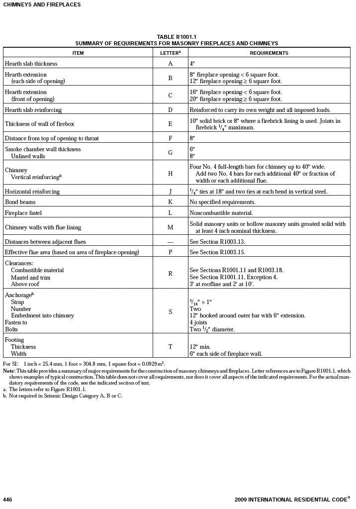
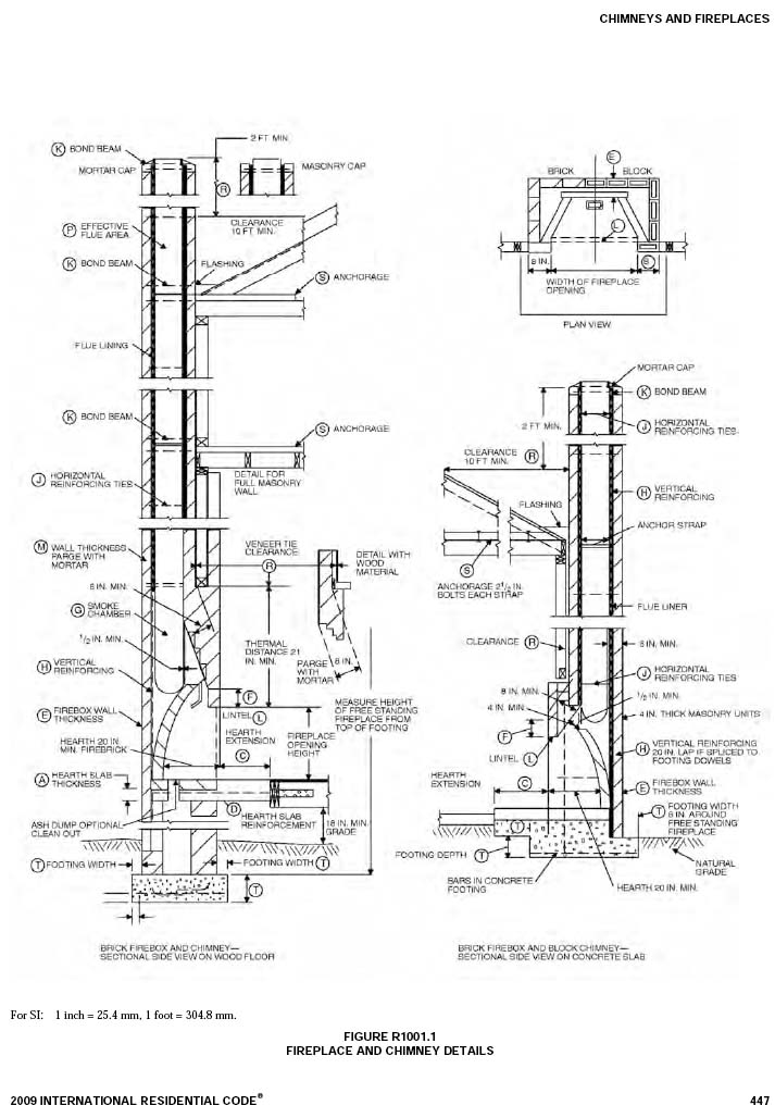
R1001.8 Smoke chamber. Smoke chamberwalls shall be constructed
of solid masonry units, hollow masonry units grouted
solid, stone or concrete. The total minimum thickness of front,
back and side walls shall be 8 inches (203 mm) of solid
masonry. The inside surface shall be parged smooth with
refractory mortar conforming to ASTM C 199. When a lining
of firebrick at least 2 inches (51 mm) thick, or a lining of vitrified
clay at least 5/8 inch (16 mm) thick, is provided, the total
minimum thickness of front, back and side walls shall be 6
inches (152 mm) of solid masonry, including the lining. Firebrick
shall conform to ASTM C 1261 and shall be laid with
medium duty refractory mortar conforming to ASTM C 199.
Vitrified clay linings shall conform to ASTM C 315.
R1001.9.2 Hearth extension thickness. The minimum thickness of hearth extensions shall be 2 inches (51 mm).
|
R1001.11 Fireplace clearance. All wood beams, joists, studs
and other combustible material shall have a clearance of not
less than 2 inches (51 mm) from the front faces and sides of
masonry fireplaces and not less than 4 inches (102 mm) from
the back faces of masonry fireplaces. The air space shall not be
filled, except to provide fire blocking in accordance with Section R1001.12.
1. Masonry fireplaces listed and labeled for use in contact with combustibles in accordance with UL 127 and installed in accordance with the manufacturer's installation instructions are permitted to have combustible material in contact with their exterior surfaces. 2. When masonry fireplaces are part of masonry or concrete walls, combustible materials shall not be in contact with the masonry or concrete walls less than 12 inches (305 mm)from the inside surface of the nearest firebox lining. 3. Exposed combustible trim and the edges of sheathing materials such as wood siding, flooring and drywall shall be permitted to abut the masonry fireplace side walls and hearth extension in accordance with Figure R1001.11, provided such combustible trim or sheathing is a minimum of 12 inches (305 mm) from the inside surface of the nearest firebox lining. 4. Exposed combustible mantels or trim may be placed directly on the masonry fireplace front surrounding the fireplace opening providing such combustible materials are not placed within 6 inches (152 mm) of a fireplace opening. Combustible material within 12 inches (306 mm) of the fireplace opening shall not project more than 1/8 inch (3 mm) for each 1-inch (25 mm) distance from such an opening.
|
2012 INTERNATIONAL RESIDENTIAL CODE - CHIMNEYS AND FIREPLACES - page 456
|
MASONRY HEATERS R1002.2 Installation. Masonry heaters shall be installed in accordance with this section and comply with one of the following:
2. Masonry heaters shall be listed and labeled in accordance with UL 1482 and installed in accordance with the manufacturer's installation instructions. R1002.4 Seismic reinforcing. In Seismic Design Categories D0, D1 and D2, masonry heaters shall be anchored to the masonry foundation in accordance with Section R1003.3.
|
Seismic reinforcing shall not be required within the body of a
masonry heater whose height is equal to or less than 3.5 times
its body width and where the masonry chimney serving the
heater is not supported by the body of the heater. Where the masonry chimney shares a common wall with the facing of the
masonry heater, the chimney portion of the structure shall be
reinforced in accordance with Section R1003. R1002.5 Masonry heater clearance. Combustible materials shall not be placed within 36 inches (914 mm) of the outside surface of a masonry heater in accordance with NFPA211 Section 8-7 (clearances for solid-fuel-burning appliances), and the required space between the heater and combustible material shall be fully vented to permit the free flow of air around all heater surfaces.
1. When the masonry heater wall is at least 8 inches (203 mm) thick of solid masonry and the wall of the heat exchange channels is at least 5 inches (127 mm) thick of solid masonry, combustible materials shall not be placed within 4 inches (102 mm) of the outside surface of a masonry heater. A clearance of at least 8 inches (203 mm) shall be provided between the gas-tight capping slab of the heater and a combustible ceiling. 2. Masonry heaters listed and labeled in accordance with UL 1482 may be installed in accordance with the listing specifications and the manufacturer's written instructions.
|
|
MASONRY CHIMNEYS
R1003.2 Footings and foundations. Footings for masonry chimneys shall be constructed of concrete or solid masonry at least 12 inches (305 mm) thick and shall extend at least 6 inches (152 mm) beyond the face of the foundation or support wall on all sides. Footings shall be founded on natural undisturbed earth or engineered fill belowfrost depth. In areas not subjected to freezing, footings shall be at least 12 inches (305 mm) below finished grade. R1003.3 Seismic reinforcing. Masonry or concrete chimneys shall be constructed, anchored, supported and reinforced as required in this chapter. In Seismic Design Category D0, D1 or D2 masonry and concrete chimneys shall be reinforced and anchored as detailed in Section R1003.3.1, R1003.3.2 and R1003.4. In Seismic Design Category A,BorC, reinforcement and seismic anchorage is not required.
R1003.3.2 Horizontal reinforcing. Vertical reinforcement shall be placed enclosed within 1/4-inch (6 mm) ties, or other reinforcing of equivalent net cross-sectional area, spaced not to exceed 18 inches (457 mm) on center in concrete, or placed in the bed joints of unit masonry, at a minimum of every 18 inches (457 mm) of vertical height. Two such ties shall be installed at each bend in the vertical bars.
|
R1003.4 Seismic anchorage. Masonry and concrete chimneys
and foundations in Seismic Design Category D0, D1 or D2 shall
be anchored at each floor, ceiling or roof line more than 6 feet
(1829 mm) above grade, except where constructed completely
within the exterior walls. Anchorage shall conform to the
requirements in Section R1003.4.1.
R1003.6 Changes in dimension. The chimney wall or chimney flue lining shall not change in size or shape within 6 inches (152 mm) above or below where the chimney passes through floor components, ceiling components or roof components. R1003.7 Offsets. Where a masonry chimney is constructed with a fireclay flue liner surrounded by one wythe of masonry, the maximum offset shall be such that the centerline of the flue above the offset does not extend beyond the center of the chimney wall below the offset. Where the chimney offset is supported by masonry below the offset in an approved manner, the maximum offset limitations shall not apply. Each individual corbeled masonry course of the offset shall not exceed the projection limitations specified in Section R1003.5.
|
|
R1003.8 Additional load. Chimneys shall not support loads
other than their own weight unless they are designed and constructed
to support the additional load. Construction of
masonry chimneys as part of the masonry walls or reinforced
concrete walls of the building shall be permitted. R1003.9 Termination. Chimneys shall extend at least 2 feet (610 mm) higher than any portion of a building within 10 feet (3048 mm), but shall not be less than 3 feet (914 mm) above the highest point where the chimney passes through the roof.
R1003.9.2 Spark arrestors. Where a spark arrestor is installed on a masonry chimney, the spark arrestor shall meet all of the following requirements: 1. The net free area of the arrestor shall not be less than four times the net free area of the outlet of the chimney flue it serves. 2. The arrestor screen shall have heat and corrosion resistance equivalent to 19-gage galvanized steel or 24-gage stainless steel. 3. Openings shall not permit the passage of spheres having a diameter greater than 1/2 inch (13 mm) nor block the passage of spheres having a diameter less than 3/8 inch (10 mm). 4. The spark arrestor shall be accessible for cleaning and the screen or chimney cap shall be removable to allow for cleaning of the chimney flue. R1003.10 Wall thickness. Masonry chimney walls shall be constructed of solid masonry units or hollow masonry units grouted solid with not less than a 4-inch (102 mm) nominal thickness.
|
R1003.11 Flue lining (material). Masonry chimneys shall be
lined. The lining material shall be appropriate for the type of
appliance connected, according to the terms of the appliance
listing and manufacturer's instructions.
1. Clay flue lining complying with the requirements of ASTM C 315. 2. Listed chimney lining systems complying with UL 1777. 3. Factory-built chimneys or chimney units listed for installation within masonry chimneys. 4. Other approved materials that will resist corrosion, erosion, softening or cracking from flue gases and condensate at temperatures up to 1,800 deg.F (982 deg.C).
R1003.11.3 Gas appliances. Flue lining systems for gas appliances shall be in accordance with Chapter 24. R1003.11.4 Pellet fuel-burning appliances. Flue lining and vent systems for use in masonry chimneys with pellet fuel-burning appliances shall be limited to the following:
2. Pellet vents listed for installation within masonry chimneys. (See Section R1003.11.6 for marking.)
2. Listed chimney liners complying with UL 641. (See Section R1003.11.6 for marking.)
THIS CHIMNEY FLUE IS FOR USE ONLY WITH [TYPE OR CATEGORY OF APPLIANCE] APPLIANCES THAT BURN [TYPE OF FUEL]. DO NOT CONNECT OTHER TYPES OF APPLIANCES.
|
|
R1003.12 Clay flue lining (installation). Clay Clay flue liners shall
be installed in accordance with ASTM C 1283 and extend from
a point not less than 8 inches (203 mm) below the lowest inlet
or, in the case of fireplaces, from the top of the smoke chamber
to a point above the enclosing walls. The lining shall be carried
up vertically, with a maximum slope no greater than 30 degrees
(0.52 rad) from the vertical. Clay flue liners shall be laid in medium-duty water insoluble refractory mortar conforming to ASTM C 199 with tight mortar joints left smooth on the inside and installed to maintain an air space or insulation not to exceed the thickness of the flue liner separating the flue liners from the interior face of the chimney masonry walls. Flue liners shall be supported on all sides. Only enough mortar shall be placed to make the joint and hold the liners in position.
R1003.12.2 Space around lining. The space surrounding a chimney lining system or vent installed within a masonry chimney shall not be used to vent any other appliance.
R1003.15 Flue area (masonry fireplace). Flue sizing for chimneys serving fireplaces shall be in accordance with Section R1003.15.1 or Section R1003.15.2.
R1003.15.2Option 2. The minimumnet cross-sectional area of the chimney flue shall be determined in accordance with Figure R1003.15.2. A flue size providing at least the equivalent net cross-sectional area shall be used. Cross-sectional areas of clay flue linings are shown in Tables R1003.14(1) and R1003.14(2) or as provided by the manufacturer or as measured in the field. The height of the chimney shall be measured from the firebox floor to the top of the chimney flue. |
TABLE R1003.14(1)
NET CROSS-SECTIONAL AREA OF ROUND FLUE SIZES
a. Flue sizes are based on ASTM C 315.
TABLE R1003.14(2)
R1003.16 Inlet. Inlets to masonry chimneys shall enter from the side. Inlets shall have a thimble of fireclay, rigid refractory material or metal that will prevent the connector from pulling out of the inlet or from extending beyond thewall of the liner. R1003.17 Masonry chimney cleanout openings. Cleanout openings shall be provided within 6 inches (152 mm) of the base of each flue within every masonry chimney. The upper edge of the cleanout shall be located at least 6 inches (152 mm) below the lowest chimney inlet opening. The height of the opening shall be at least 6 inches (152 mm). The cleanout shall be provided with a noncombustible cover.
|
FLUE SIZES FOR MASONRY CHIMNEYS

FIGURE R1003.18
CLEARANCE FROM COMBUSTIBLES
R1003.18 Chimney clearances. Any portion of a masonry
chimney located in the interior of the building or within the
exterior wall of the building shall have a minimum air space
clearance to combustibles of 2 inches (51 mm). Chimneys
located entirely outside the exterior walls of the building,
including chimneys that pass through the soffit or cornice, shall
have a minimum air space clearance of 1 inch (25 mm). The air
space shall not be filled, except to provide fire blocking in
accordance with Section R1003.19.
1. Masonry chimneys equipped with a chimney lining system listed and labeled for use in chimneys in contact with combustibles in accordance with UL 1777 and installed in accordance with the manufacturer's installation instructions are permitted to have combustible material in contact with their exterior surfaces. 2. When masonry chimneys are constructed as part of masonry or concrete walls, combustible materials shall not be in contact with the masonry or concrete wall less than 12 inches (305 mm) from the inside surface of the nearest flue lining. 3. Exposed combustible trim and the edges of sheathing materials, such as wood siding and flooring, shall be permitted to abut the masonry chimney side walls, in accordance with Figure R1003.18, provided such combustible trim or sheathing is a minimum of 12 inches (305 mm) from the inside surface of the nearest flue lining. Combustible material and trim shall not overlap the corners of the chimney by more than 1 inch (25 mm).
R1003.20 Chimney crickets. Chimneys shall be provided with crickets when the dimension parallel to the ridgeline is greater than 30 inches (762 mm) and does not intersect the ridgeline. The intersection of the cricket and the chimney shall be flashed and counterflashed in the same manner as normal roof-chimney intersections. Crickets shall be constructed in compliance with Figure R1003.20 and Table R1003.20.
CRICKET DIMENSIONS
|
FACTORY-BUILT FIREPLACES
R1004.2 Hearth extensions. Hearth extensions of approved factory-built fireplaces shall be installed in accordance with the listing of the fireplace. The hearth extension shall be readily distinguishable from the surrounding floor area. R1004.3 Decorative shrouds. Decorative shrouds shall not be installed at the termination of chimneys for factory-built fireplaces except where the shrouds are listed and labeled for use with the specific factory-built fireplace system and installed in accordance with the manufacturer's installation instructions. R1004.4 Unvented gas log heaters. An unvented gas log heater shall not be installed in a factory-built fireplace unless the fireplace system has been specifically tested, listed and labeled for such use in accordance with UL 127.
FACTORY-BUILT CHIMNEYS R1005.2 Decorative shrouds. Decorative shrouds shall not be installed at the termination of factory-built chimneys except where the shrouds are listed and labeled for use with the specific factory-built chimney system and installed in accordance with the manufacturer's installation instructions. R1005.3 Solid-fuel appliances. Factory-built chimneys installed in dwelling units with solid-fuel-burning appliances shall comply with the Type HT requirements of UL 103 and shall be marked "Type HT" and "Residential Type and Building Heating Appliance Chimney."
|
For SI: 1 inch = 25.4 mm.
FIGURE R1003.20
CHIMNEY CRICKET
|
and shall be marked "Residential Type and Building Heating
Appliance Chimney." Chimneys for use with open combustion chamber appliances installed in buildings other than dwelling units shall comply with the requirements of UL 103 and shall be marked "Building Heating Appliance Chimney" or "Residential Type and Building Heating Appliance Chimney." R1005.4 Factory-built fireplaces. Chimneys for use with factory- built fireplaces shall comply with the requirements of UL 127. R1005.5 Support. Where factory-built chimneys are supported by structural members, such as joists and rafters, those members shall be designed to support the additional load. R1005.6 Medium-heat appliances. Factory-built chimneys for medium-heat appliances producing flue gases having a temperature above 1,000 deg.F (538 deg.C), measured at the entrance to the chimney shall comply with UL 959.
EXTERIOR AIR SUPPLY
|
R1006.3 Clearance. Unlisted combustion air ducts shall be installed with a minimum 1-inch (25 mm) clearance to combustibles for all parts of the duct within 5 feet (1524 mm) of the duct outlet. R1006.4 Passageway. The combustion air passageway shall be a minimum of 6 square inches (3870 mm2) and not more than 55 square inches (0.035 m2), except that combustion air systems for listed fireplaces shall be constructed according to the fireplace manufacturer's instructions. R1006.5 Outlet. Locating the exterior air outlet in the back or sides of the firebox chamber or within 24 inches (610 mm) of the firebox opening on or near the floor is permitted. The outlet shall be closable and designed to prevent burning material from dropping into concealed combustible spaces.
|

Buckley Rumford Fireplaces
Copyright 1995 - 2013 Jim Buckley
All rights reserved.
webmaster